Currently reading: How to build a BTCC race engine
Many teams in the British Touring Car Championship run a ‘generic’ engine supplied by Swindon Powertrain. This season, one of them will have us to thank

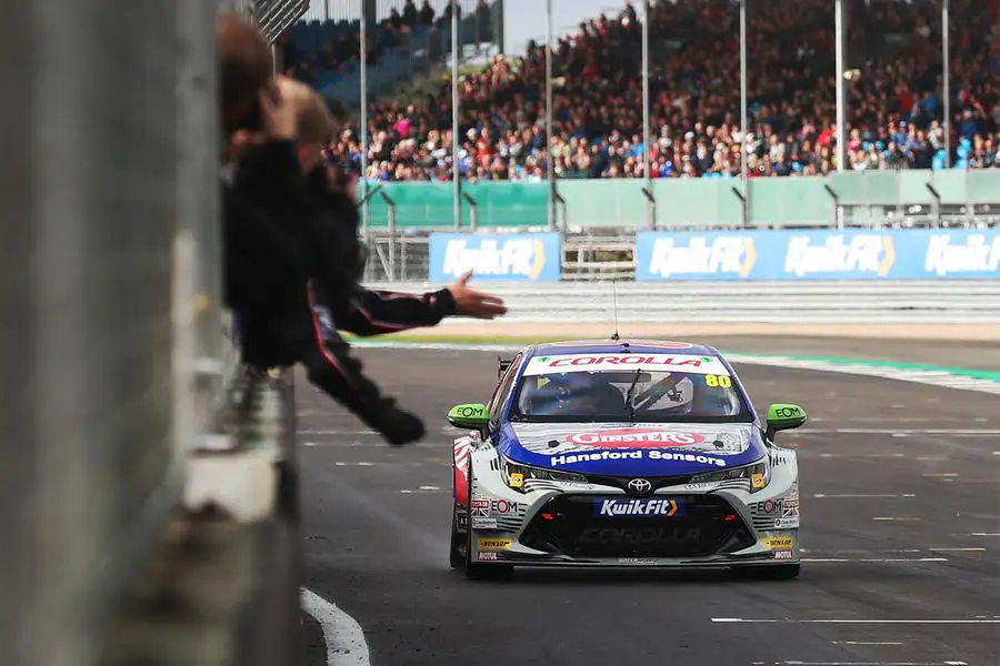
At the start of each British Touring Car Championship race, something like 13,000bhp is unleashed before an excited crowd. Engine builders, although quietly confident, may admit to the odd flutter of butterflies, too, because their efforts are vital to every driver’s chances of success. Since 2011, when BTCC organiser TOCA established the New Generating Touring Car (NGTC) rules, teams have been able to use a race-prepared factory engine or a generic TOCA unit supplied by Swindon Powertrain. All use an Xtrac six-speed sequential gearbox no matter their engine choice.

The ‘unbranded’ TOCA engine is based on a standard 2.0-litre, direct-injection, 16-valve, turbocharged four-cylinder engine purchased from a major road car maker. Swindon has built nearly 200 examples since 2011, each one taking around 45 hours to complete. The race engines are equipped with ‘drive-by-wire’ electronic throttles under the control of a Cosworth ECU that every car must use, although engine builders can modify the mapping.

Power is quoted by TOCA as 350bhp-plus, but Swindon says they’re technically capable of 400bhp and Maxed Racing gives the output of its Vauxhall Astras as ‘around 380bhp’. The engines have a life of 5000km (3100 miles) between services and will cover 3500km (2174 miles) in a season. Installation in the car can be either transverse or longitudinal in order to suit both front-wheel drive and rear-wheel drive.

7 Bttc cars

The great thing about writing a story on race engine building is the chance to get your hands dirty – except I don’t, because everything in Swindon’s engine shop is so clean. There isn’t time to help with an entire 45-hour build, but I do have a crack at a couple of crucial stages.

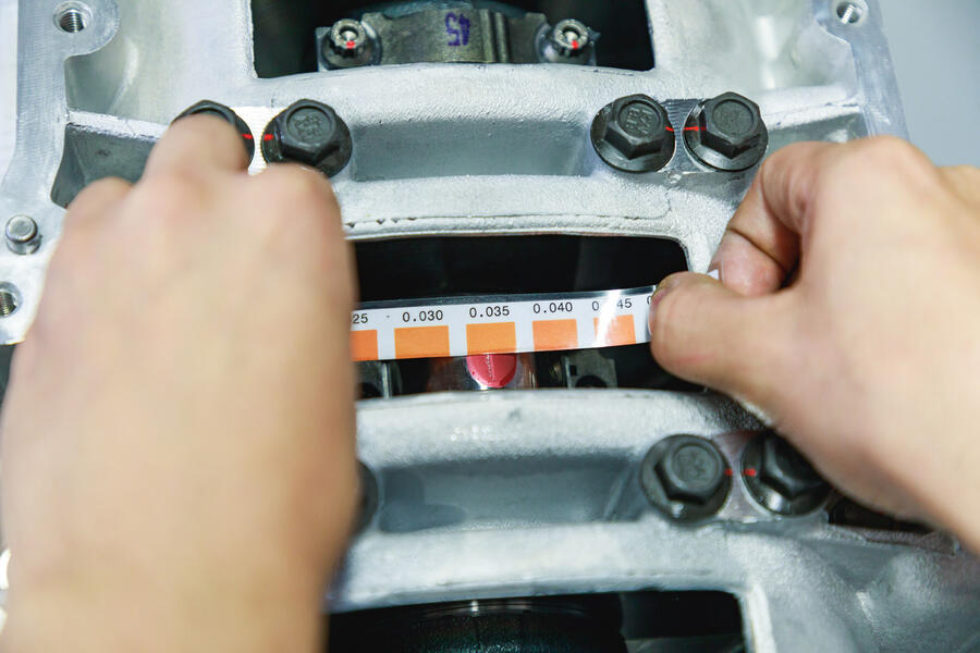
First off is checking the clearance on the crankshaft main bearings (which support the crankshaft in the crankcase) and on the big-end bearings (which attach the connecting rods with their pistons) to the crankshaft. This clearance is crucial. Too tight and the bearings could fail catastrophically, too loose and they would wear prematurely with potentially the same end result.

Back to top

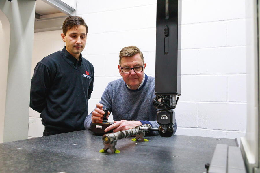
With engine builder Tiago Lopes instructing and watching my every more, I check the clearances with Plastigauges, which look like thin threads of plasticine. When a short length is laid across each bearing journal and its cap tightened to the correct torque, the Plastigauge gets squashed flat. Measuring its flattened width against a scale gives the clearance in the bearing.

ARP competition bolts are much stronger than standard ones, which aren’t up to dealing the massive forces exerted in a race engine. I follow instructions to the letter, doing everything by the Swindon book. For example, slippery bolts are removed with a magnet rather than your fingers to avoid dropping them onto the finely ground bearing surface of a crank journal or into the engine, and threads on the connecting rods are covered with plastic tubes during the process to avoid damaging the crankshaft.

6 Measuring clearances

The next stage I try is installing the chain drive to the camshafts. The camshafts open and close valves to let fuel and air in and exhaust gas out. Their design is one of the most crucial aspects of getting maximum power and torque from the engine, and the position in which they are installed relative to the crankshaft is critical. With gauges to set the correct position of the cams and number one piston at the top of its throw (top dead centre), I install the chain, plastic tensioners and gears on the cams using positioning marks for alignment.

Back to top

The cams are designed with CAD (computer-aided design) tools and made in-house on CNC (computer numerical control) machines, and their exact profile is a closely guarded secret. Machining interrupts the grain structure of the steel, so they are rough cut then stabilised at 580deg C for five hours before being quenched in oil and finished.

A brief trip to the CMM (co-ordinate measuring machine) room gives an insight into the incredibly precise checking of components. We then head to the engine dynamometer cell, where the engines are calibrated, run in and tested. It takes about an hour to set the engine up on the dyno with cooling and fuel systems. Temperatures are measured in the engine, in the intercooler and in two places on the exhaust. Air conditioning is used to maintain 15deg C at the air intake of all test engines.

3 Tom ingram

Two engineers control every run, one operating the dyno and the other using a laptop to keep an eye on the data and vital signs. Engines have to conform to an average performance curve, and if they don’t, they’re opened up again. A ‘sacrificial’ development engine is about to get the treatment.

If these engines sound good from the trackside, being three metres from one running flat out on a dyno is something else. The already-warm engine fires and is run up to a screaming 6950rpm behind the test cell window and the exhaust temperature rises to a glowing 720deg C, but the power readout has been discreetly deleted from the laptop screen.

Back to top

All is well. I’m told that it has been a long time since an engine has ‘let go’ under test, so repeatable and controlled is the build process.

1 Jesse crosse using measuring machine

Final calibration work is done inside the car, because of the slight variation in installations, and that includes adjusting the throttle map to suit an individual driver’s preferences.

When the 2020 BTCC cars fire up on the grid for the first time, it will be fun to think I played an ever-so-tiny part in putting one of them there.

The BTCC goes hybrid

The BTCC is due to be electrified in 2022 through the addition of mild-hybrid technology. The 60V systems will consist of an electric motor inside the mandatory Xtrac gearbox (adding 7.5kg to the transmission), a battery and cabling.

The complete system will add a total of 64kg – 10kg less than the maximum ‘success ballast’ weight used previously. Away from the gearbox, the cars will require some changes to cooling and intercooler hoses, an upgraded Antares electronics suite from Cosworth and some new electrical connections.

Regenerative braking is adjustable by the drivers, who will have an extra 40bhp or so available to aid overtaking or defending for up to 15 seconds per lap once the first lap has been completed. Pit-lane driving will be under electric power only and the hybrid system’s performance can be calibrated to suit wet conditions.

Back to top

1 Cosworth hybrid drawing

The system has been developed by Cosworth, which says the main benefit to drivers will be at lower revs, bringing the engine up into the ‘turbo window’ more quickly. Simulation shows that with two cars accelerating out of Copse at Silverstone, a hybrid would gain eight metres using hybrid drive before they reach the braking zone.

The new units will also change the shape of the racing. BTCC bosses will stop using success ballast, instead using the hybrid units to reduce boost levels for successful machines.

The units can be leased from Cosworth for £20,500 per season, making the hybridisation cost-effective for teams that won’t need whole new powertrains. Track testing is due to begin at some point this year.

READ MORE

Behind the scenes at the BTCC's mobile technical centre 

BTCC 2020: New look for title-winning BMW squad 

BTCC delays first three rounds as UK motorsport halted

Join the debate

Comments
2
Add a comment…
david RS 9 April 2020

Why not the same cars?  

Why not the same cars?


LP in Brighton 9 April 2020

Base engine?

It would be interesting to know which manufacturer supplies this standard base engine - also which manufacturers use their own units in the series?  Presumably the standard ECU is designed to ensure horsepower parity between all engines.